Did you ever have a pneumatic conveying project that didn’t work the way you thought it might? Maybe what worked on paper didn’t hit the target convey rate in your plant? There could be a lot of reasons why the project missed the mark, but one very simple reason that is often overlooked relates to convey line elbows.
We know what you’re thinking — “Elbows? How could something so simple make that much of a difference?” What we’ve come to find is that convey line elbows look simple, but they can become a conveying headache if laid out incorrectly. When it comes to elbows in piping a conveying system, there are four essential factors that require particular attention and foresight before a system’s design is green-lit for purchase:
- The number of elbows
- The distance to the first elbow from the pick-up point
- The distance between each elbow
- The size of the elbow
In this entry to the AZO blog, we aim to provide insight into how critical it is to keep these points in mind. While equipment manufacturers like AZO certainly use algorithms and programs to determine how the components of a convey system fit together, it is really experience that ensures a system design will work exactly as expected. Just because the math adds up, doesn’t mean it will work in the real world.
This is how elbow placement becomes such a “hidden” or overlooked concern. Without further ado, here’s how elbows in pneumatic conveying systems challenge the design of piping components:
Proper layout of a convey line considers elbow placement
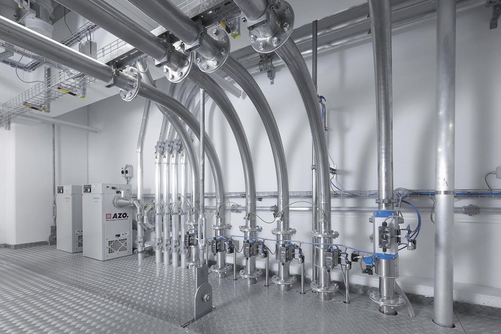
If a new conveying system is being put into an existing plant, there are obviously a few things to keep in mind. There are going to be existing walls, ductwork and process piping to design around. Elbows in the convey line are necessary to get around these “obstacles,” but every elbow slows material velocity and should be considered when designing a pneumatic conveying system.
Determining where they can and can’t be placed in the pipe run is critical for your material’s velocity and ultimately the success of the system design.
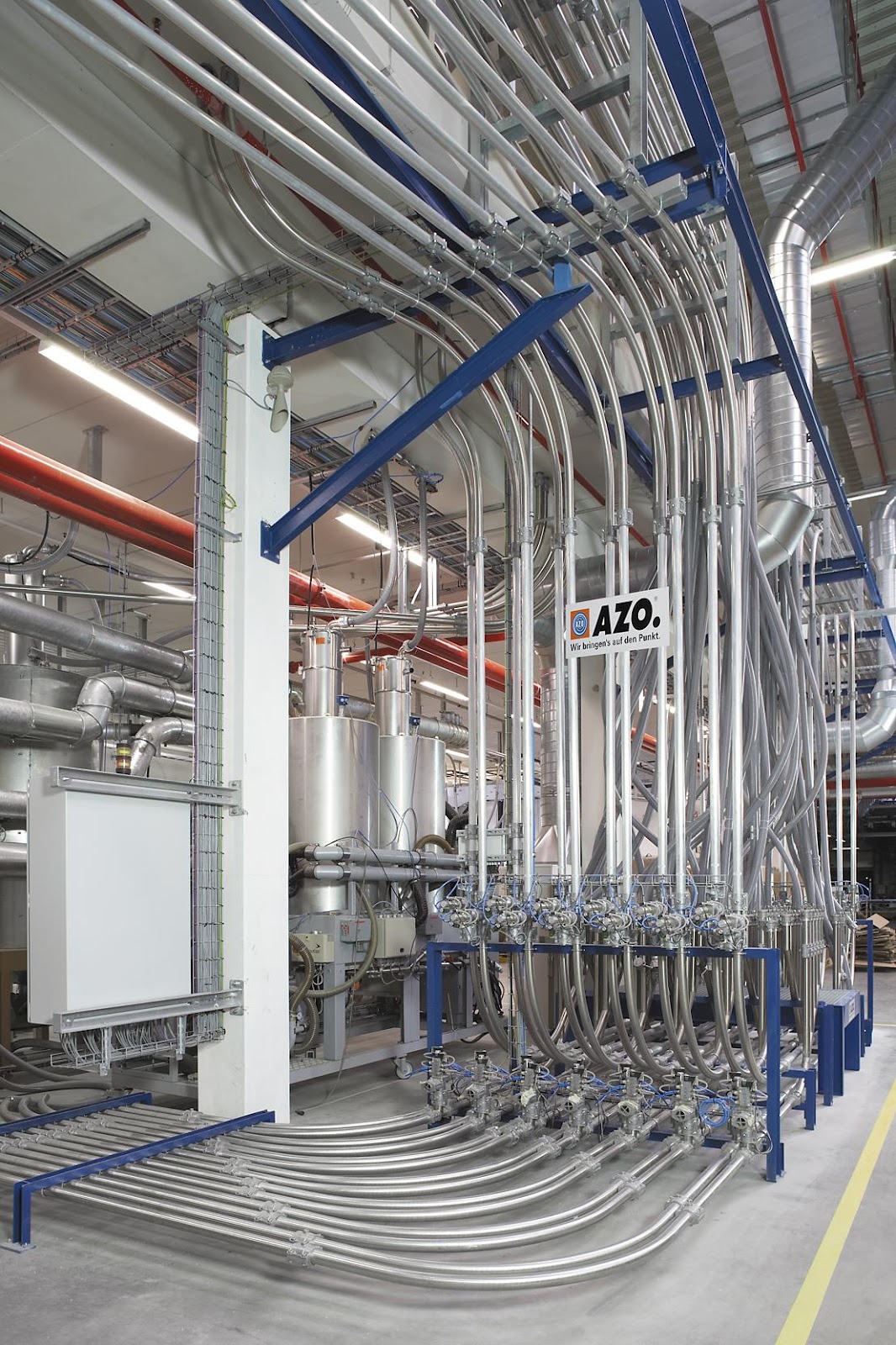
Efficient layout of a convey line considers elbow arc and radius
Elbows are typically available in 30-, 45-, 75- and 90-degree configurations. As material flows through a pipe, it will physically hit the pipe wall of every elbow. This causes material to lose both energy and speed. A 45-degree elbow (as compared to a 90-degree elbow) will reduce the impact against the pipe wall and will therefore decrease the amount of energy lost.
A separate consideration from observing the arc of the elbow is observing the radius of the elbow. Both relate to the elbow’s size, but an elbow’s radius specifically speaks more to the sharpness of the turn within the elbow. In other words, an elbow with a 3-foot radius has a sharper turn than one with a 6-foot radius.
A sharper elbow (one with a smaller radius) will cause material to experience a greater impact against the elbow wall. This also translates to a greater loss of momentum for the material. Just as how a driver slows more for a sharp curve on a road, conveyed material will be slowed more by a sharp elbow than a gradual elbow (one with a larger radius).
Therefore, to maintain material momentum passing through an elbow, use an elbow with the largest radius and smallest arc possible.
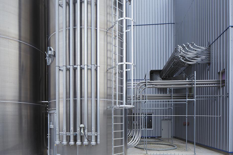
Distance in a convey line ensures speed and velocity of material
As mentioned above, material speed slows when passing through an elbow. Once the elbow is cleared, straight pipe will facilitate an increase in material speed. It takes distance (from one elbow to the next in the line) for the material to regain free-flowing velocity. Without proper distance between elbows, the material slows progressively. It then cannot recover free-flowing velocity and could possibly stop, plugging the convey line.
Elbows must not be placed too close to the pick-up point
Putting an elbow too close to the pick-up point (before the material can reach free-flowing velocity) is a surefire way to kill the momentum of your material. A material that slows to the point that it is no longer suspended in the airflow is a material no longer in motion.
Placing an elbow too close to the pick-up point could also lead to a material build-up within the pipe. When that material begins to move again (following air pressure build-up) there is a good chance that it will move too fast. Material that is sensitive to high velocities (easily broken or with high fat content) will not respond well to this type of pressure fluctuation. You should maximize the distance between the product pick-up point and the first elbow to ensure the material has reached free-flowing velocity.
Experience shows that elbow placement is critically important in pneumatic conveying. Start the convey line with a nice long section of straight pipe before your material encounters the first elbow. Too many elbows, too close together will slow down any system and could cause line plugs. If this can be avoided, try to use large radius pipe or smaller arc elbows to minimize momentum loss. If in doubt, physically test your design to validate your assumptions. While elbows are simple, they can play an essential role in the success of every pneumatic conveying system.
For more content related to conveying systems, check our free conveying guide. Specific benefits of conveying modes, how to avoid product smearing and more helpful topics are included in “Choosing The Right Pneumatic Conveying Method For Process Material Handling.” AZO has seven decades of experience shaping ingredient automation, so feel free to contact our sales team for any questions on how to help your plant and processes run smoothly.